Lift Engine
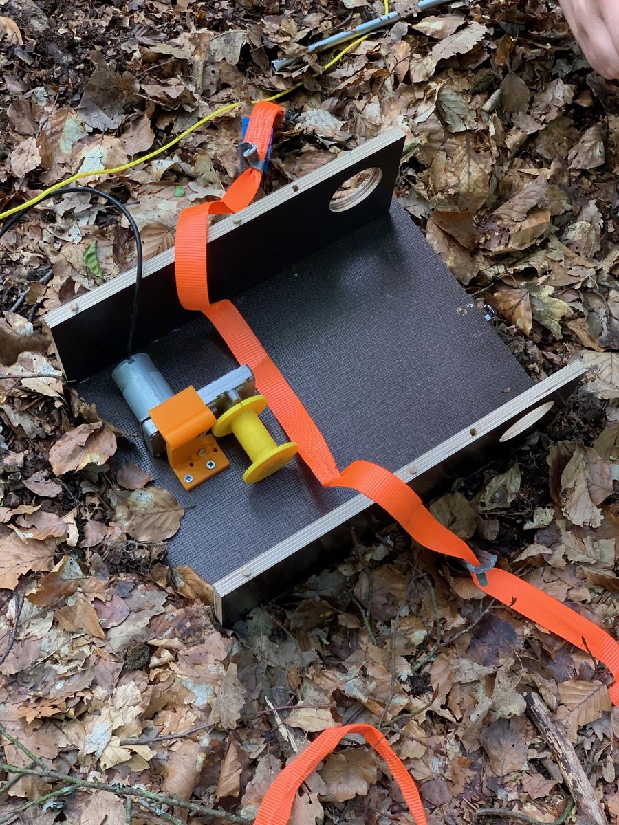
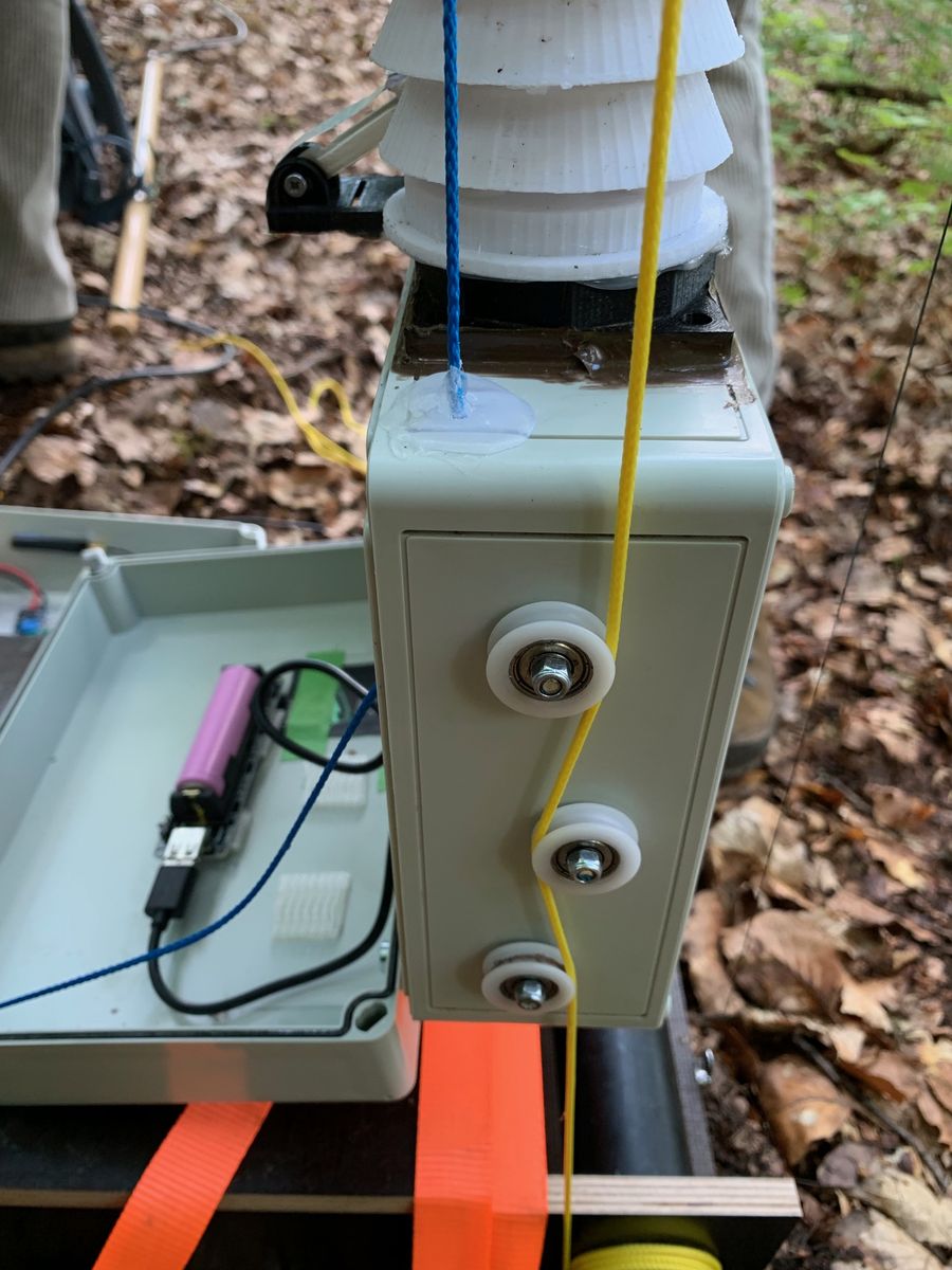
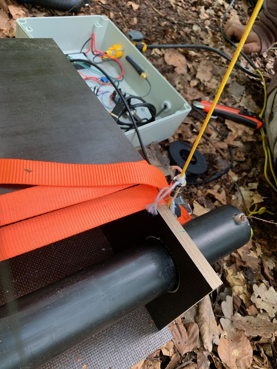
The construction of the ground station for the tree lift is largely self-explanatory. The Waterproofed phenol faced birch plywood panels form the structural framework. In this open box, the motor and mounting bracket, the deflection roller and the tension roller made of PU tubing are installed.
For the counter bearing in the treetop 2 Waterproofed phenol faced birch plywood plates are fixed with 4 rubber tension cables and tension belts at a suitable position in the treetop. The counter bearing has two pulleys.
Parts List
Motorbox
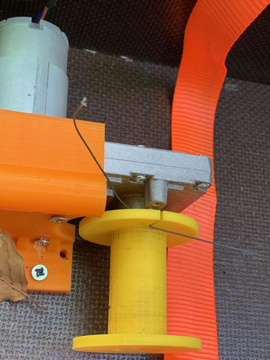
- 1 DC motor up to 24(36)V, with worm gear
-
Waterproofed phenol faced birch plywood wooden plates
- 1 groundplate 18 mm 26.50 x 36,50 cm
- 2 sideplates 12 mm 34.00 x 12.50 cm
- 1 topplate 18 mm 26.50 x 24.00 cm
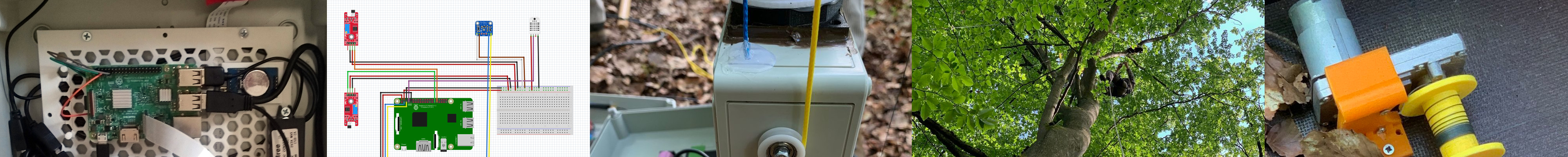
- 1 motormount (3D printed) Motor Mount
- 1 reel (3D printed) Motor Mount
- 2 welftnuts M4 12
- 1 cable with connectors (rain-waterproof)
- 1 return pulley + mount
- 1 drain pipe (to tighten the wires)
- 1 anchor (to stop the drain pipe from rolling loose)
- 2 ground anchors
- 1-2 span belts
- screws
- 6 (connecting the wooden plates)
- 1 M4 16 (motor - motormount)
- 2 M4 12 (motor - motormount)
- 2 M4 25 (motormount - groundplate)
- 6 wooden dowels (optional)
- glue
Topmount
- 2 plates
- 4 rubberbands
- 1 eye bolt + corresponding nut
- 1 span belt
- 2 return pulleys + mount
Others
- wires 3mm
- fishing line at least 10kg
Construction Scheme
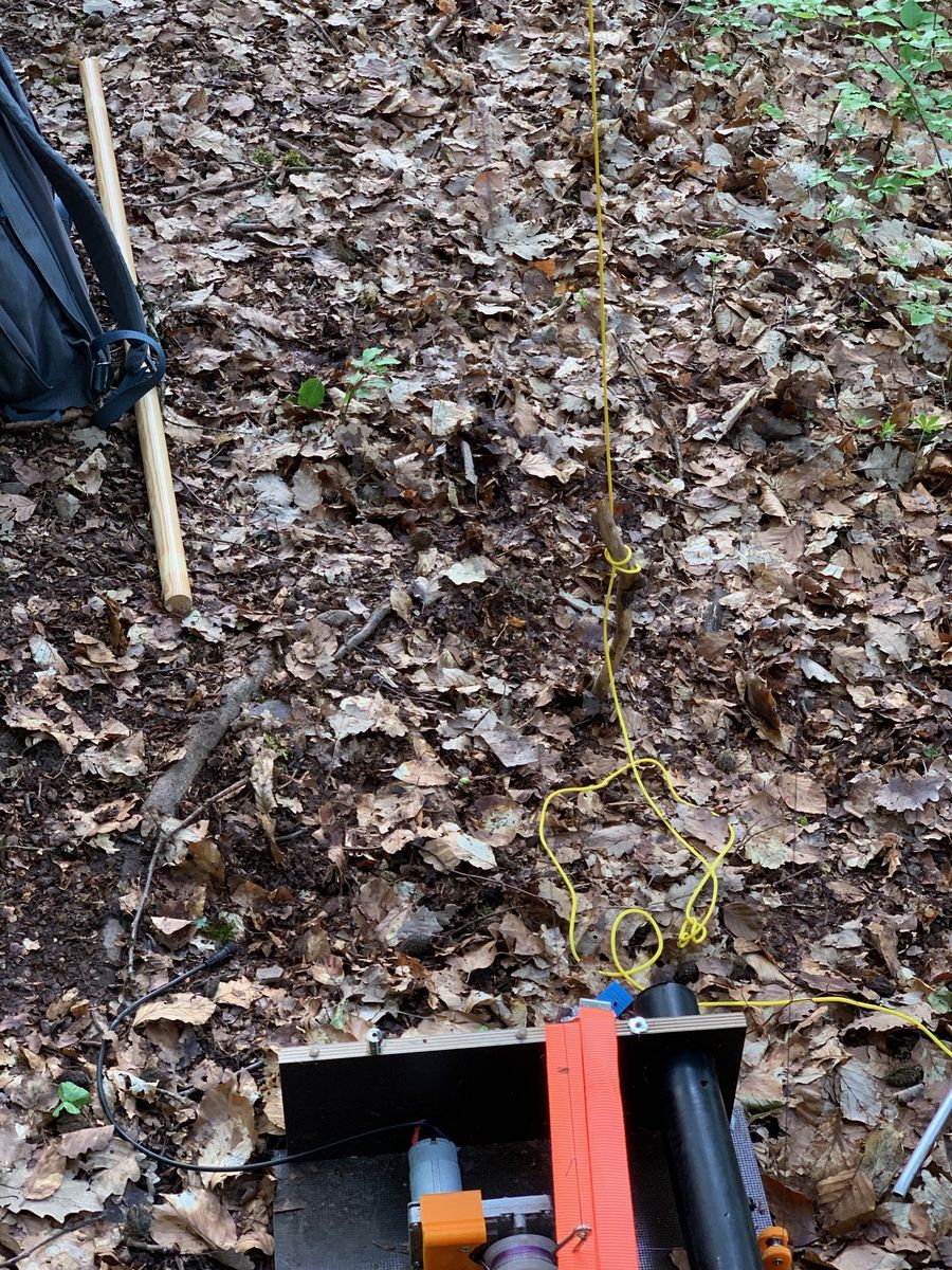
Deployment of a Lift Station
It is not possible to completely standardize the construction of a Sensorlift, since the installation of the components depends very much on the in situ conditions. Nevertheless, two areas have to be distinguished, the treetop and the ground station, which have to be processed in a sensible sequence.install
Deployment of the Base station